H-Bridge Step-Through
<< click to return to front page
<< click to return to content page
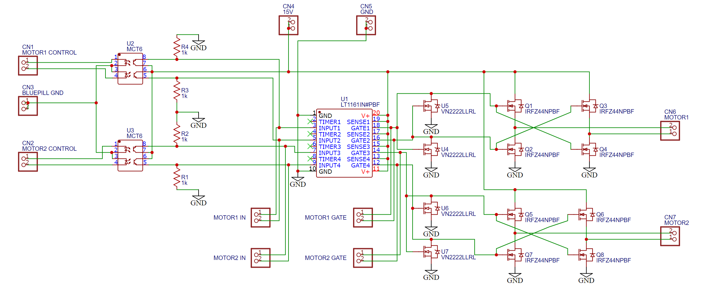
In this tangent I want to step through the final H-Bridge schematic shown below, for any interested readers or future students of ENPH 253. This “guide” assumes basic knowledge of electrical components + reading schematics.
This H-Bridge schematic is the one I used in my motor drivers for ENPH 253:
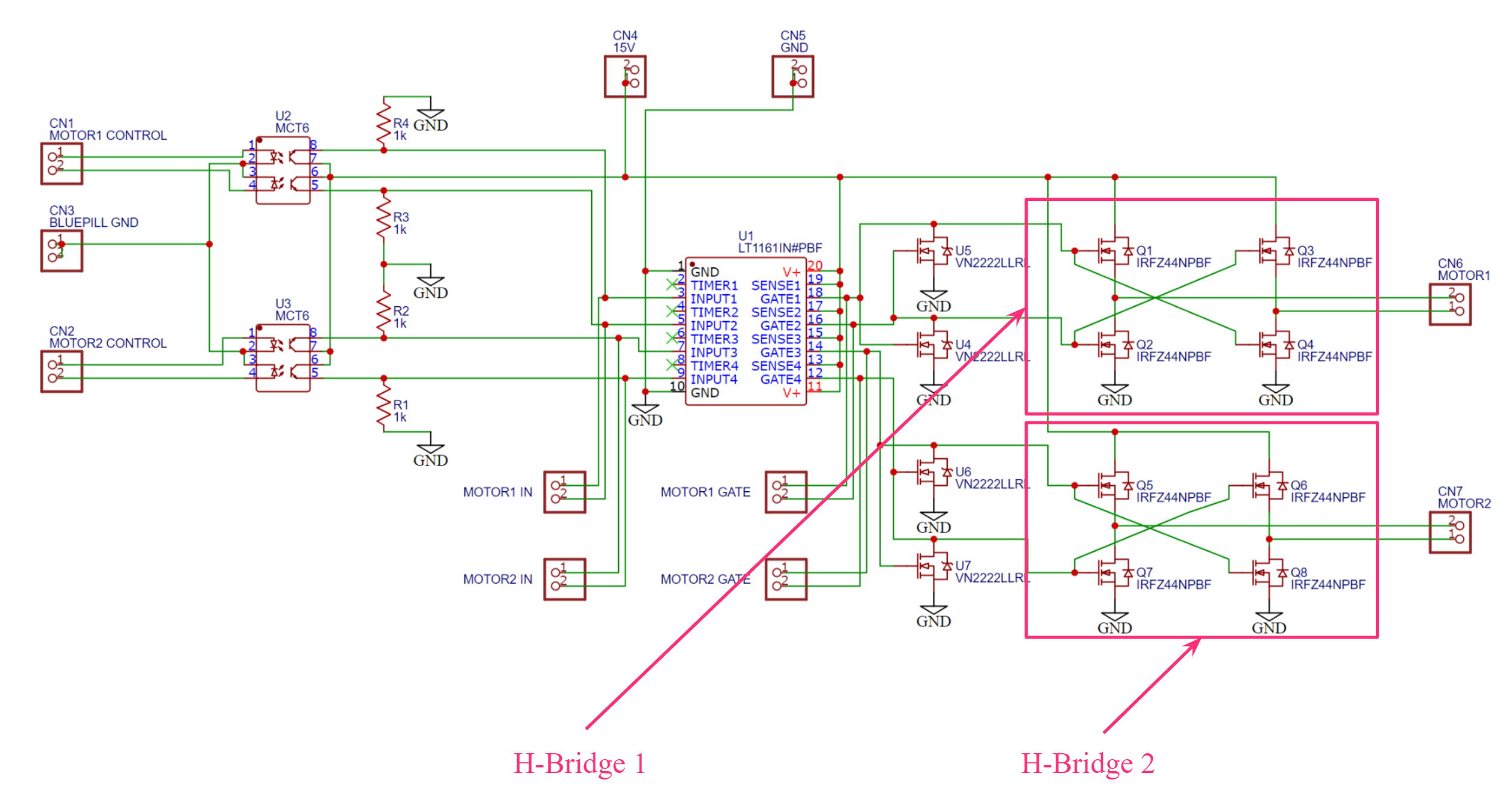
All that an H-Bridge does is control the direction of which current flows through a load. In the case of our robot, we need 2 H-Bridges, one for each motor, to control if it goes forward or backwards. Here is the final dual-H-bridge circuit:
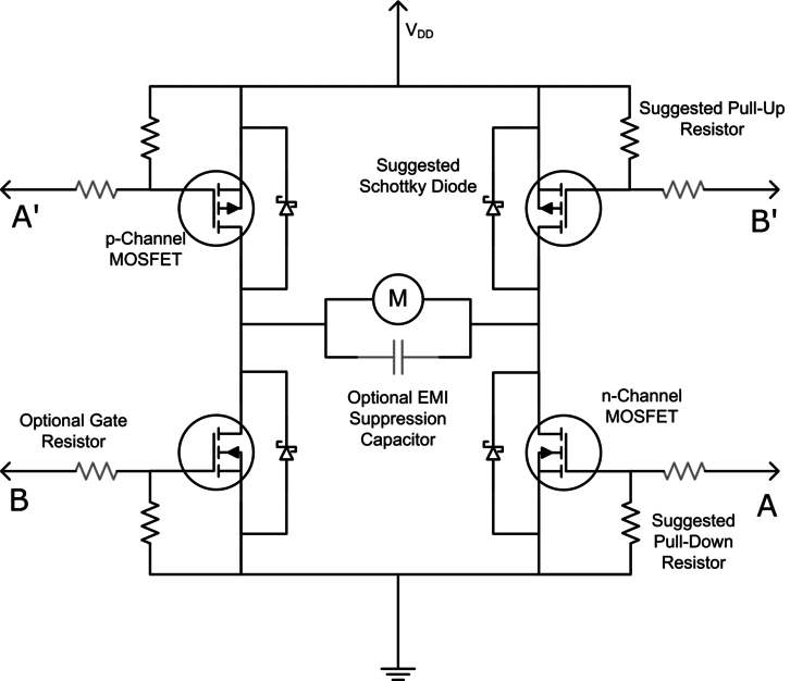
If you search up “H-Bridge” you’ll likely find some image like this, with 4 MOSFETS and a motor sitting in between, creating an H-shape.
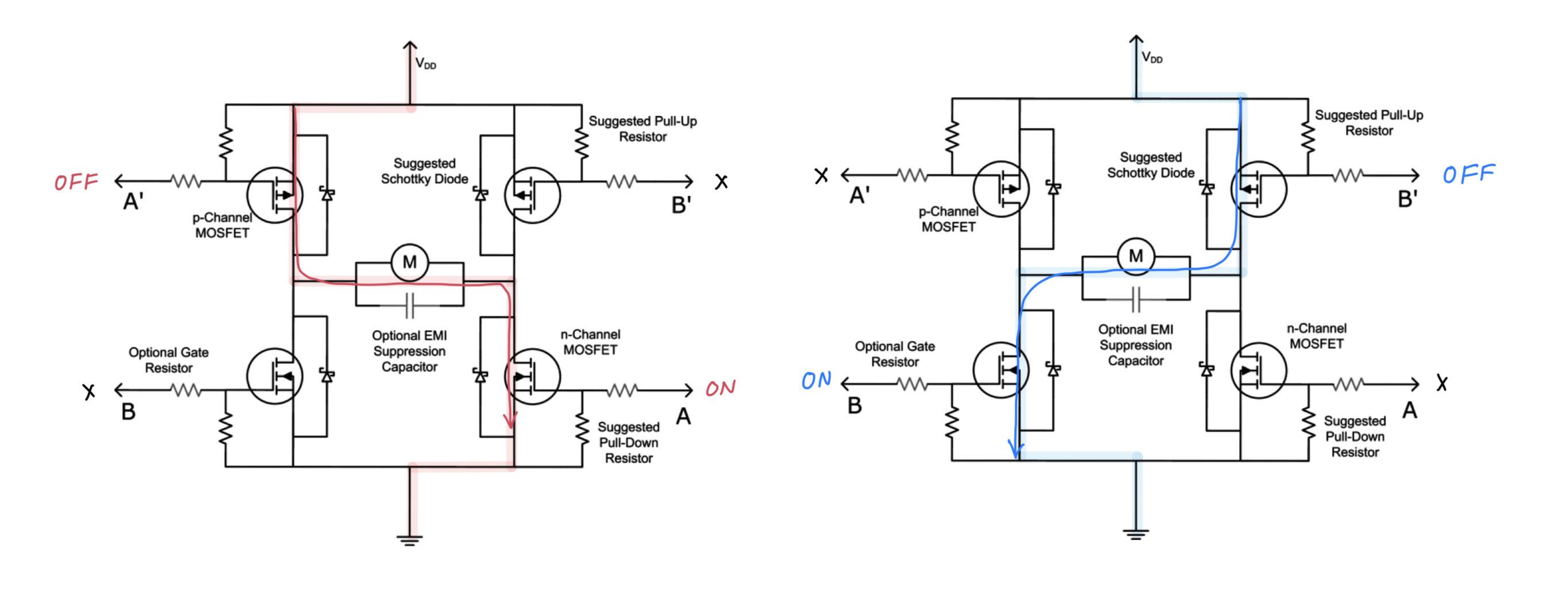
By selectively toggling on/off certain MOSFETS, the H-Bridge is able to switch the direction of current running through the motor. In the red case, the current flows from left-to-right, while in the blue case, the current flows from right-to-left. Only two MOSFETS are to be on at a time, one before the motor and one after the motor.
If this is all we need, what is the point of all the other circuitry shown originally? Aren’t there already 2 H-Bridges, in the schematic already?
While that is true, there is one immediate difference — on the high-side (meaning the half which sits before the motor), our H-Bridges use N-Channel MOSFETS, while most H-Bridges on a quick google search use P-Channel MOSFETS
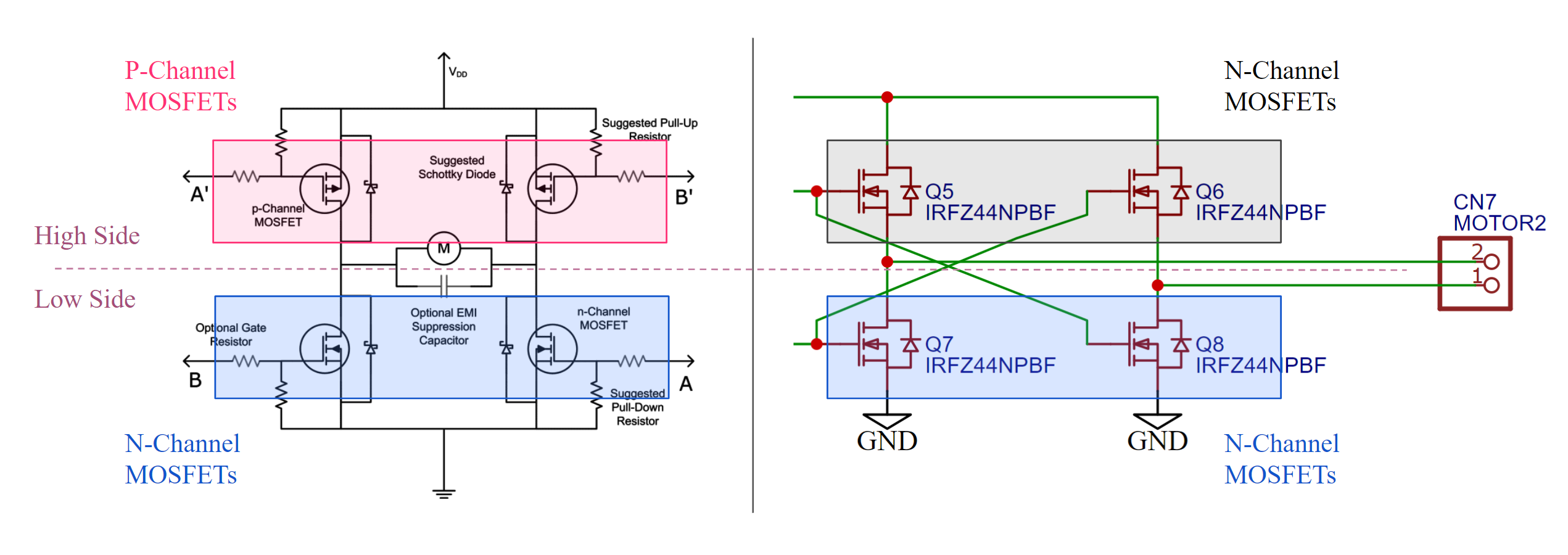
Arguments can be made for either P or N, but the primary reason N-MOSFETS were used on the high-side of the H-Bridge was because of their lower ON resistance (less power draw for high-current motor driving) and faster switching speed (required for driving with PWM).
However, using N-MOSFETS on the high side means that their gate needs to be driven with a voltage higher than the voltage we want to run on the motor. Bad news is that our motors operate at 12V, which is much higher than what any standard microcontroller can provide on an output.
This is where we introduce the LT1161 MOSFET Gate Driver, specifically made to drive high-side N-MOSFETS. It sits directly in between of the control stage (the data lines which tell the H-bridge which direction to drive the motor in), and the H-bridges themselves. The orange lines, or gate output lines, show how the gate driver connects to the MOSFETS.
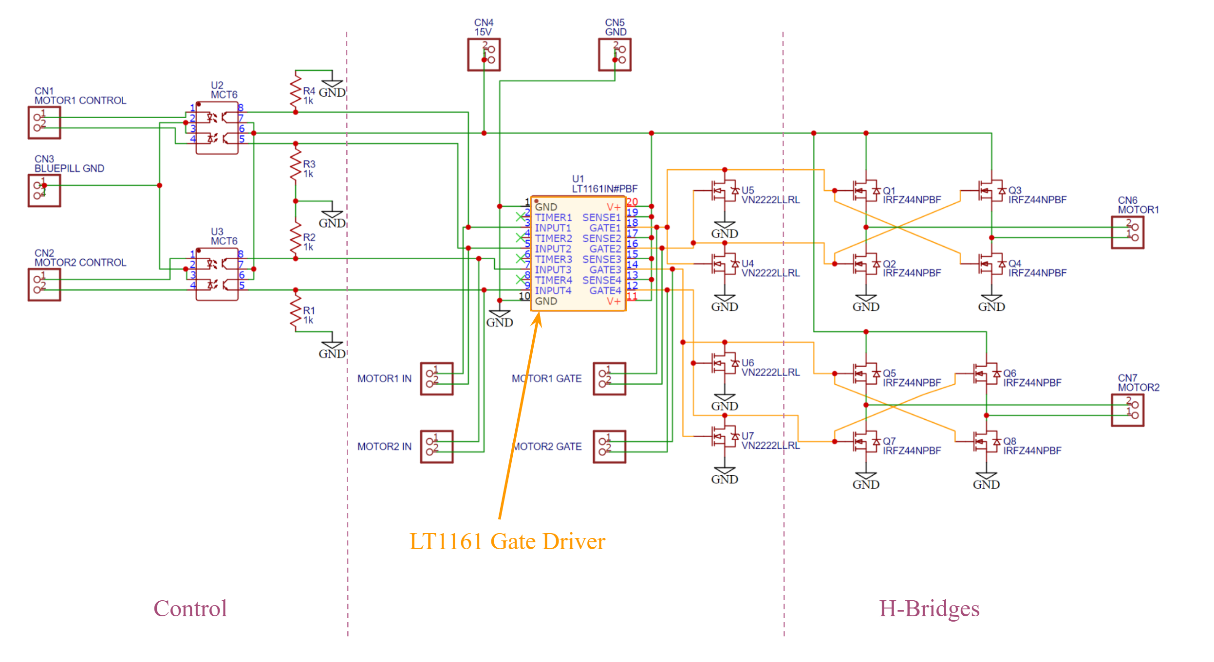
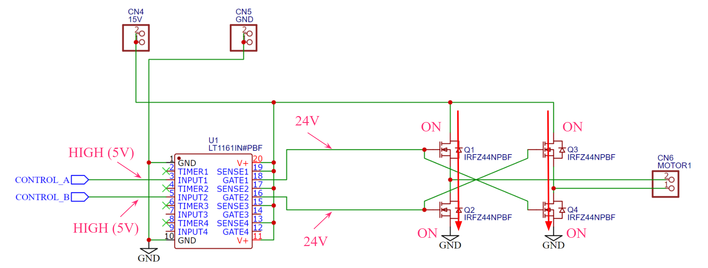
This gate driver chip uses internal charge pumps so that if, say INPUT1 is on, then GATE1 will be at the supply voltage (12V), plus another 12V. This puts 24V on the gate of all MOSFETS when needed, which solves our high-side problem.
If I only drew out what I’ve explained, we’re currently at this stage. Moving from left to right, we have the input lines controlled by some microprocessor, the gate driver, which step up those control line voltages, and the MOSFETS, arranged in an H-bridge configuration which then go out to CN6/CN7, where motors will connect.
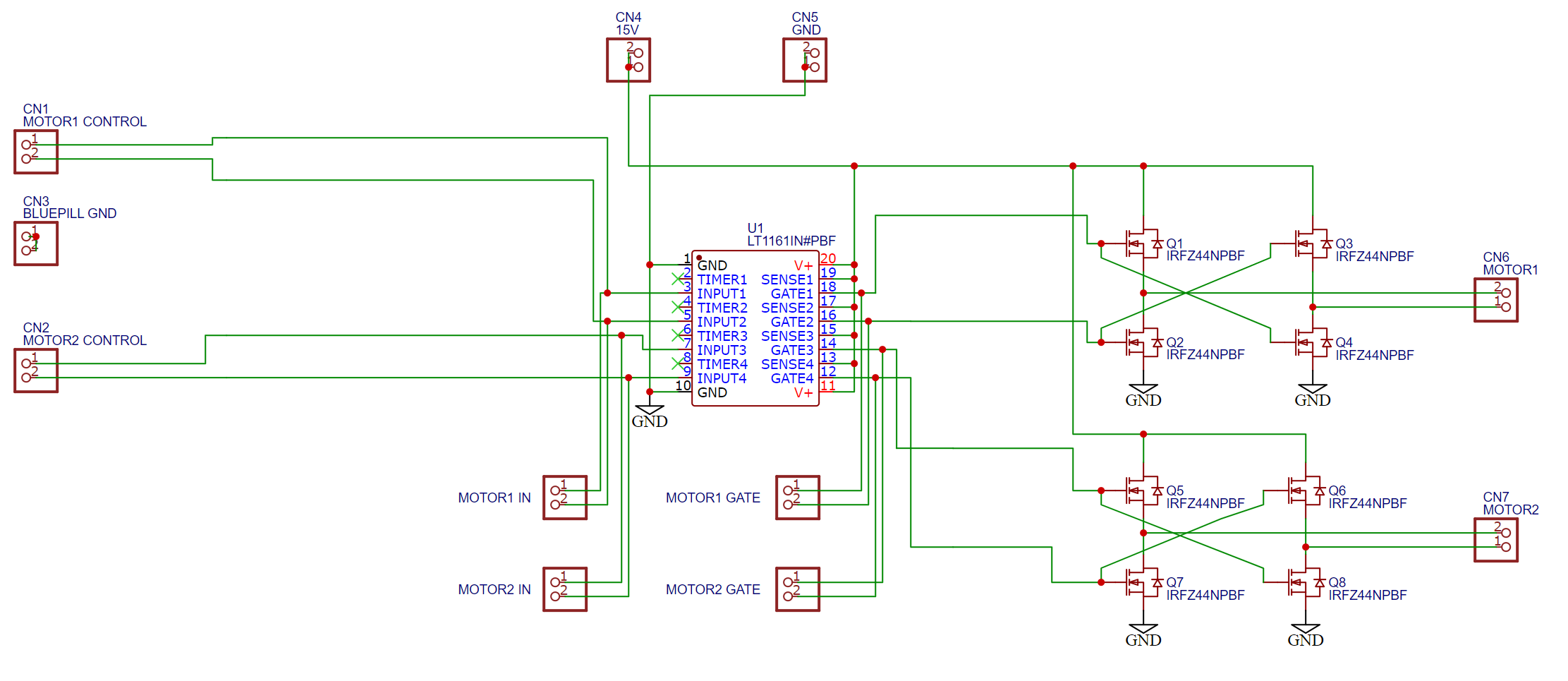
And this is now back to a fully functioning H-Bridge! All we did was take out the P-MOSFETS, which requires us to add the gate driver to drive the high-side N-MOSFETS. But this still isn’t the full circuit shown originally.
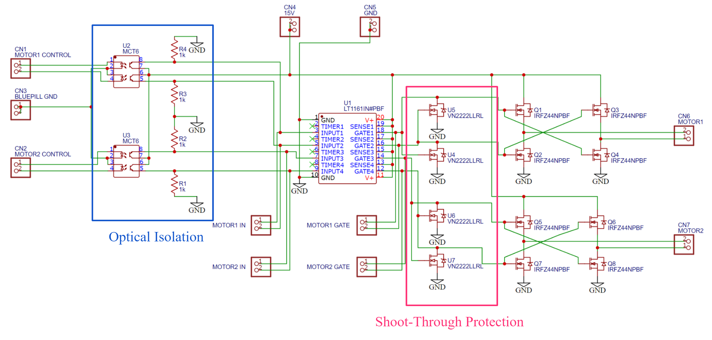
There are two niceties existing in the final schematic, shoot-through protection and optical isolation.
Shoot-Through Protection: Suppose that, through some microcontroller or programming error, both control lines to one H-Bridge go high. This should never happen anyways since it doesn’t make sense for the microcontroller to tell the motor to go forwards (by setting CONTROL_A on) and backwards (by setting CONTROL_B on) at the same time — it should always be one or the other.
With CONTROL_A high, the top-left and bottom-right N-MOSFETS turn on. With CONTROL_B high, the top-right and bottom-left N-MOSFETS turn on. All 4 N-MOSFETS are on, and so current can flow directly from power to ground, drawn by the red arrows. This is devastating for both the power electronics and the MOSFETs themselves, so we want some sort of safeguard to avoid this.
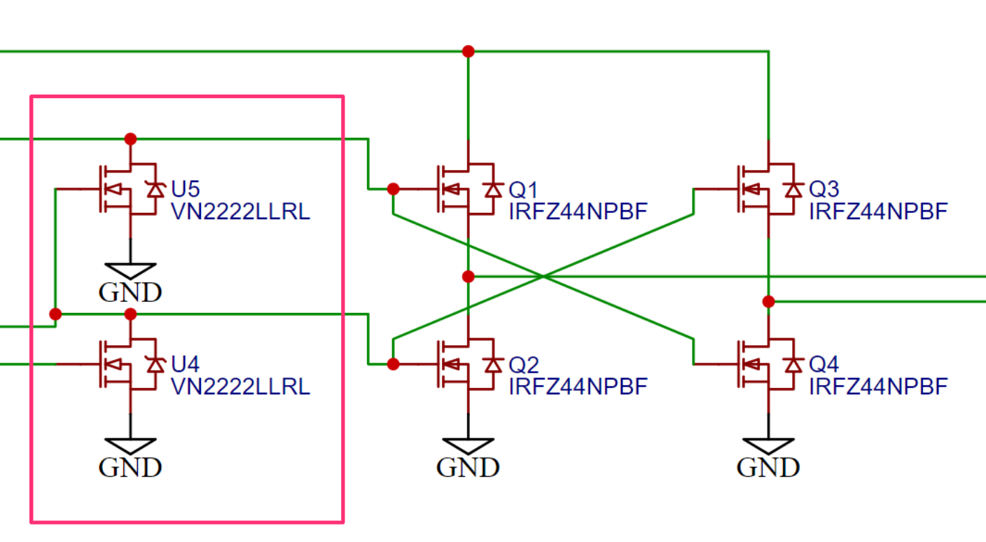
This is where shoot-through protection is added, with two new low-current MOSFETS that sit before the 4 N-MOSFETs themselves.
This time, if both control lines are accidentally enabled:
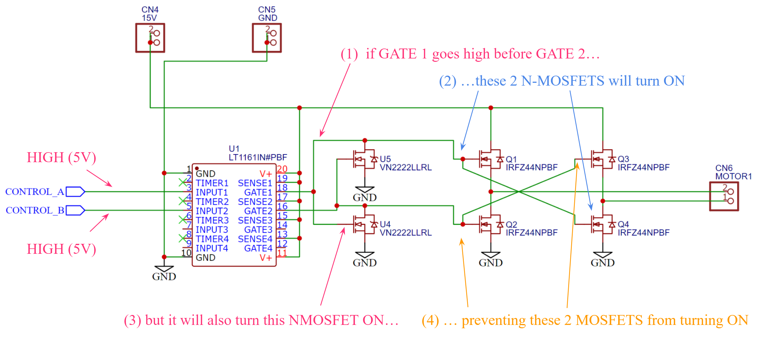
Suppose CONTROL_A and CONTROL_B are both high, which lead to both GATE1 and GATE2 being high. For some brief period of time, perhaps on the microsecond timescale, one of the GATE outputs were on a little earlier than the other. For the sake of example, suppose that GATE 1 goes high before GATE 2. As expected, it will turn on the top-left and bottom-right N-MOSFETs (blue).
However, GATE 1 also drives the gate of U4, one of our new shoot-through protection MOSFETs (VN2222L), which also turns on. This forcefully pulls GATE2 down to ground (GND), preventing the top-right and bottom-left N-MOSFETS from turning on (orange).
But wait, isn’t CONTROL_B still on, meaning there’s 24V on GATE2? Doesn’t pulling the pin down to ground still short circuit? Fortunately, the LT1161 has mechanisms to handle this and will not burn if we short one of its pins to ground.
I recommend stepping through the circuit but now assuming that GATE2 goes high before GATE1 does, and you should find the opposite result happens. Overall, this shoot-through mechanism works by implementing that when one output is on, the other output is locked to zero, regardless of what its control pin input says.
Optical Isolation:
We’ve talked about some microprocessor / MCU writing to the control pins of the H-Bridge (CONTROL_A, CONTROL_B from before). Simply by looking at the full schematic below, we can see that optical isolation divides the control lines from the rest of the H-Bridge circuit:
But why would we need some sort of isolation, and how does it work? To answer the first question, I need to zoom out briefly.
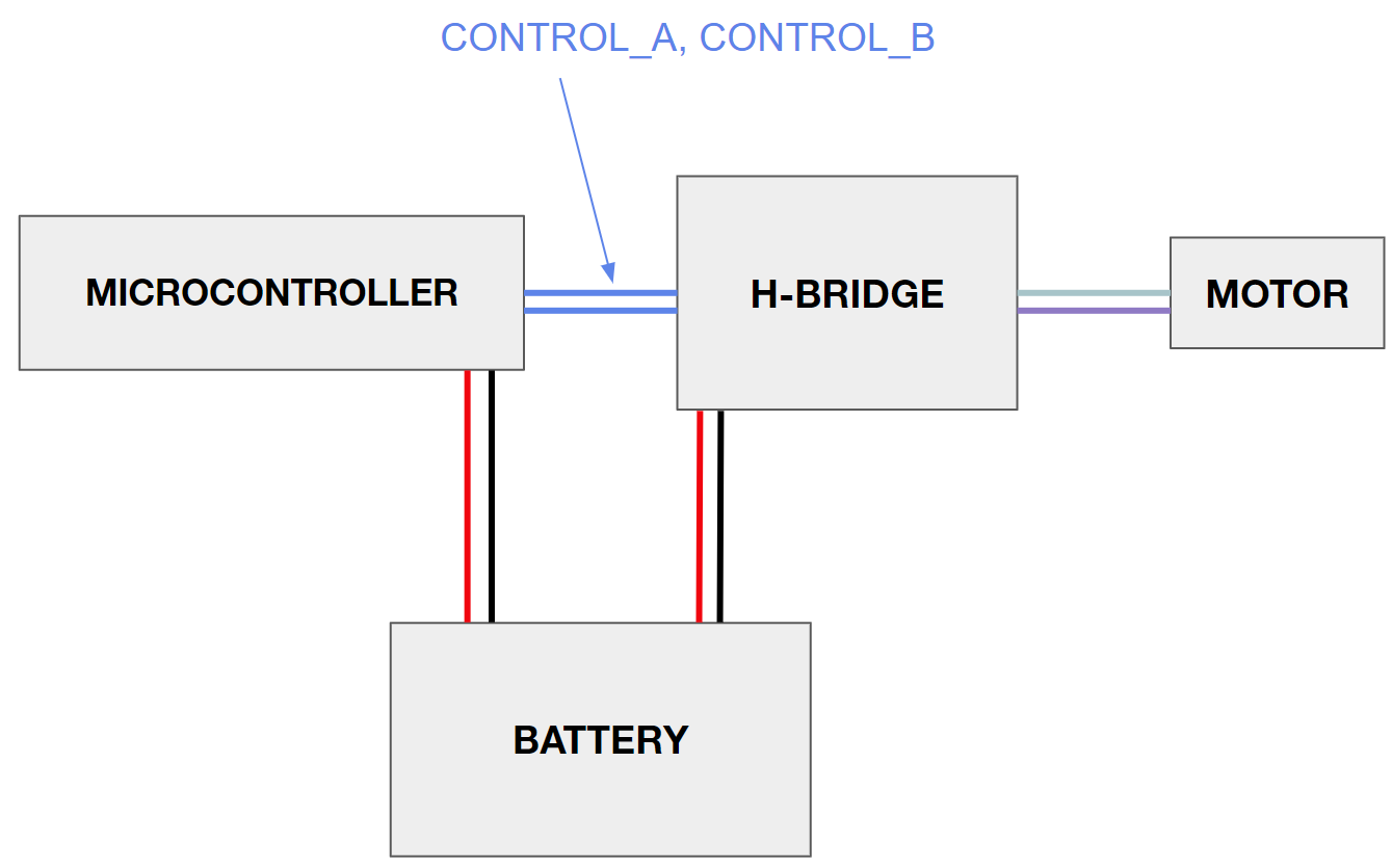
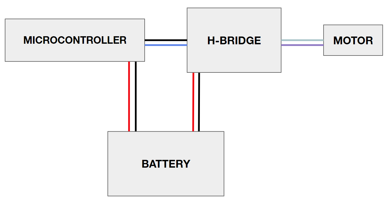
Consider the high-level drawing of the microcontroller and H-Bridge, powered by the same battery — this means that they share grounds. The microcontroller writes to CONTROL_A and CONTROL_B on the H-Bridge to change the direction of the motor.
Now, suppose we want the motor to spin in some direction — say CONTROL_A is off and CONTROL_B is on. The microcontroller, programmed with such instructions, has an internal MOSFET which pulls the CONTROL_A down to ground (line is now black):
Let’s quickly zoom into the H-Bridge and see what is going on. The motor is spinning, meaning high current flows from the power rail, down through one high-side MOSFET, through the motor, and down through one low-side MOSFET, and down to ground (the triangular GND marker):
.png)
But, where is ground? Well, it’s all the way back at the battery — so this high current needs some path back to it. It has two possible paths:
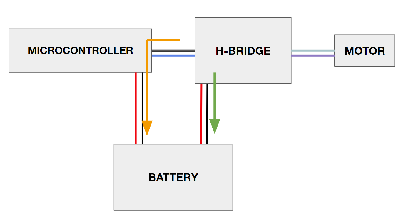
The most straightforward is that the high current goes from the H-Bridge board, to the ground line which connects it to the battery (green path). However, there’s nothing stopping this current from going through the CONTROL_A line (which is essentially a ground line), and down to battery through the microcontroller’s ground line (orange path).
The reason the orange path exists is through something called a ground-loop, and would also occur if CONTROL_A was on and CONTROL_B was off. Now, the microcontroller used in ENPH 253, the STM32 Bluepill (BP), is a very noise-sensitive device. If large current spikes or noise make their way to the ground (GND), the BP can often crash or restart abruptly. With such an existing ground loop, high motor current taking the orange path to ground passes the sensitive Bluepill, leaving it susceptible to erratic behavior, and could even damage it. Moreover, regardless of ground loops, motor grounds also tend to be noisy anyways, and so it is ideal if we can keep it away from the Bluepill.
Now that I have clarified the why, we can get into the how. We need some way to isolate these grounds and get rid of the orange path — this can easily be done with two batteries:
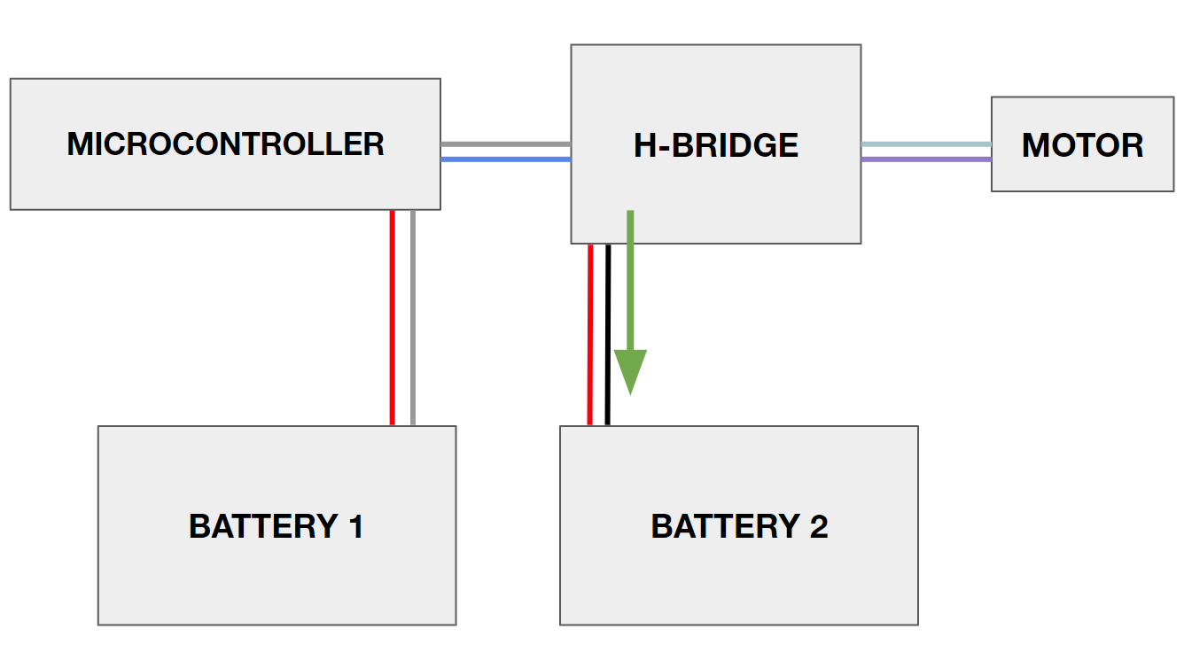
Now there are two grounds, colored by grey and black, and we can see that there is no more ground loop! However, there is a new issue: When the microcontroller tries to turn say, CONTROL_A on, it will raise the line to 3.3V referenced to BATTERY 1’s ground (gray). To the H-Bridge, which is referenced to BATTERY 2’s ground (black), this 3.3V relative to ground 1 will not be 3.3V relative to ground 2. In other words, the H-Bridge has no idea what the microcontroller is trying to instruct because they are referenced differently.
Fortunately, this new referencing issue is easier to solve than the ground loop problem — the solution is to introduce something called an optocoupler.
An optocoupler is a LED + phototransistor pair, neatly fit into an IC package:
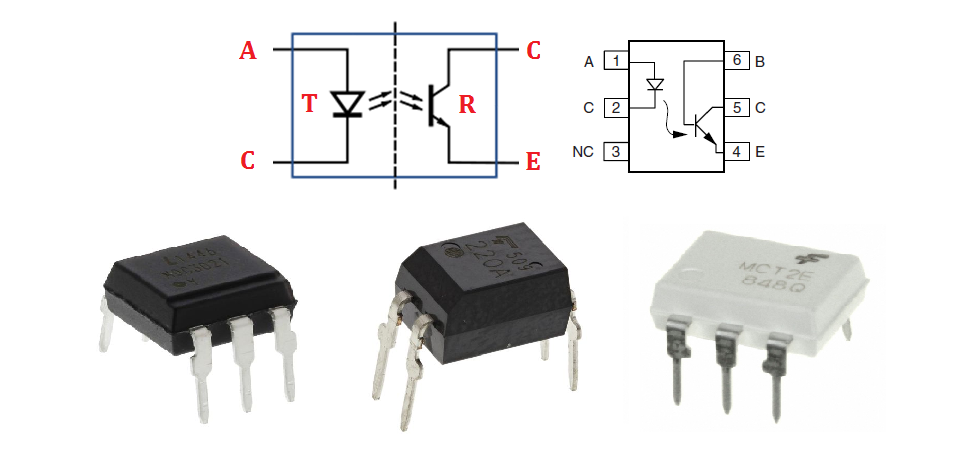
The LED’s inside these optocouplers emit IR, so don’t except cutting one open and seeing bright lights inside.
With an optocoupler, the more current you pass through the IR LED, the more IR light is emitted, which means more IR light is absorbed by the phototransistor, and more current can pass through the phototransistor. Overall, this device couples currents by IR light without any electrical contact, which is why it is a method of optical isolation. Now, let’s look at how it is added to the H-Bridge circuit:
We have one optocoupler LED per control pin, and the corresponding phototransistor’s emitter connected to each LT1161 input, with a 1 kilo-ohm pull-down resistor to the motor ground. The collector of the phototransistor is connected to the motor driver power supply (12V):
.png)
The “off” case is quite simple — suppose Line 2 on MOTOR2 CONROL is off. Then, the bottom LED is off, no IR light is emitted, and so no current flows through the phototransistor. The emitter is now floating, but with the pull-down resistor to ground (R1), INPUT4 is grounded. Notice that it is grounded to the motor’s ground, not the microcontroller ground, and so the gate driver will read “off”.
The “on” case is pretty simple too — suppose Line 2 on MOTOR CONTROL is on (3.3V, with respect to the BLUEPILL GND). Then, current flows through the LED as indicated by the pink path:
.png)
Every optocoupler (we use the MCT6) has a specified current transfer ratio (CTR), which is the ratio between LED current and phototransistor current. Say that the current through the LED is 20 mA. If the CTR is 50%, then 10 mA will flow through the phototransistor, and down through R1 to the motor ground (blue path). With 10 mA across the 1 kilo-ohm resistor, we know that 10V will be present on the INPUT4 line, and so the gate driver will read “on”.
10V is a lot different than the 3.3V output given by the microcontroller, but these are both above the “on” threshold for the gate driver, so they have the same effect.
Finally, we have arrived at the final dual motor driver schematic shown originally. I hope this guide helped simplify the H-Bridge and best of luck to any future ENPH 253 students!